Micro Pillars
Fabrication tutorial
Basic substrate for hydrophobic surface
Basic substrate for hydrophobic surface
Here is the procedure to create 10 µm high Su-8 pillars on silicon substrate. We start with a p-type silicon substrate 500 µm thick. Then we have to find the proper mask for the pillars. In our lab we have three types:
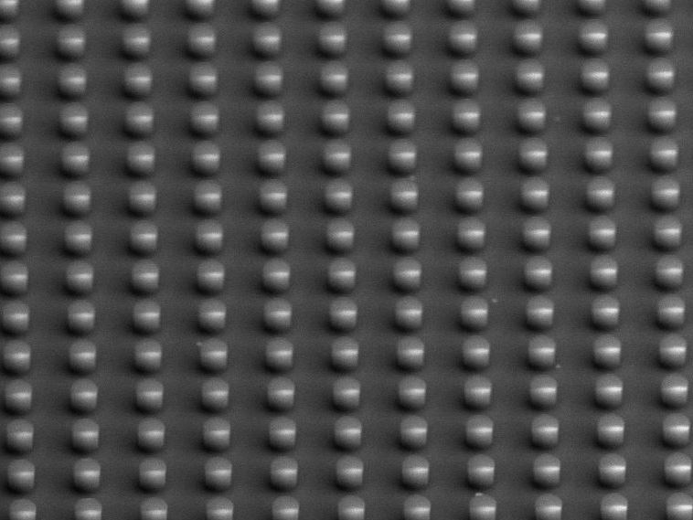
2 µm diameter pillars with 4 µm distance side-side (or 6 µm center to center)
6 µm diameter pillars with 12 µm distance side-side (or 18 µm center to center)
10 µm diameter pillars with 20 µm distance side-side (or 30 µm center to center)
The ratio between diameter and density determines the hydrophobic property of the substrate. The contact angle with bare pillars will be around 120°, while it will increase up to 170° when coated with Teflon. In this experiment we will use a Pillar Mask with 6 µm diameter and 12 µm distance. The mask is 2 inches wide, so accordingly we will choose a wafer of the proper dimension.So we choose one quarter of wafer (simply cutting it by tweezers, following the crystal sections).
We start with the SU-8 spinning. This resist is a negative one, with high density. It must be kept in the fridge, at 11 °C, then it has to be put outside until it comes at the room temperature before the use. After the use it has to be put again in the fridge. This in fact is a resist that is very sensitive to the temperature variation. So, after the bottle of SU-8 is at the right temperature, we put the piece of silicon on the spinner and we drop the resist in the centre, until it covers almost the whole piece. We set the spinning parameter to 4000 rpm for 70 seconds. The layer of SU-8 will be around 10 µm thick. While the spinning is working, we have to put the hot plate at 65°C. in fact the pre-bake of the resist requires a temperature of 90°C for 45 minutes, but since the resist is sensitive to the changes in T, we start at 65° and, after 3 minutes, we change to 90° for the rest of time.
Now the samples can be irradiated with UV. Since it is a negative resist, the illuminated part will remain on the structure. Since I want to create pillars, I need a mask that will have transparent circles and the rest dark. The mask aligner requires two things: a mask and a sample. So it provides two different holders, one for the mask and one for the samples. Both come in two dimensions, for bigger or smaller samples/masks. The instrumentation comes with a sort of tutorial: at each step there will be a flashing led indicating the next button to press in order to continue the operation. So, in order to start we have to switch on the main power, then we have to open the N2 valve and finally the UV lamp. The heating of the lamp will require 1 hour to achieve the regime, take note of this. After the UV lamp is ready, we can switch on the mask aligner system. Then, we can change the mask holder, set the align parameters, modify them etc. Since we want a good resolution of our structure, we want the mask to be as close as possible to our sample. So we choose a vacuum alignmen, the mask and the sample will be put in close contact via vacuum. After the set of all the parameters, the holders will be inserted in the chamber and the last button will flash: expose. Pressing it will start the exposure of the lamp, this time set to 35 seconds. It is very important to set the right amount of time of the UV lamp; if time is low the rays will not penetrate deep in the samples, leaving some layer unexposed. If the time is too much, the rays will penetrate too deeply in the sample, enlarging the irradiated zone. During the lamp exposure the users will have to wear the protective goggles and warn the nearby people that there is an exposure in progress; it is also sufficient not to look at the lamp.
Now the first step for the resist inversion is done. The second part will require a post-exposure-baking. We need again the hot plate at 65°C and we have to put the sample on it for 15 minutes. During this process, the irradiated part will change the structure, making it resistant to the SU-8 developer. In fact, after the last baking, we have to prepare two beakers, one with SU-8 Developer, the other with IPA. We have to put the samples in the Developer for 5 minutes, while shaking up and down and circularly the beaker: this will help the developer to remove the unexposed part of resist. Then we put the sample in IPA for 30 seconds just to wash away the developer and we dry the sample with N2 gun. It is important to use low pressure on the gun, since the resist is fragile the air jet mustn’t be strong. The sample is now ready, we can see it at the microscope. Probably there will be darker zone on the sample, basically on the borders: in these zones the pillars will have lower quality or will be more dense since the layer of SU-8 was less homogenous.
Now that the pillars are fabricated, we can add some steps with the RIE. For example we want to make them super-hydrophobic. Or maybe we want to create some roughness on the top of the pillars to make them more suitable to cell grasp. These two processes are quite simple and require some plasma. So from the menu we select Handling – Loadlock - Venting to open the Loadlock. From here we have to remove a metal ring, used to keep the wafer in position, then we remove the silicon wafer. This wafer is used for the O2 cleaning process. So, we can put our personal wafer on the stage, block it with the ring and put our samples on it. We will start with the peeling, that is we want to etch the surface of the pillars to make them rougher. This process requires two gas, O2 and Ar. To be sure we can open all the valves, then the system will select only the needed ones. We will use 100 V for the cloud and 50 V for the acceleration of the plasma. When it starts, we will see also the plasma light from the window of the chamber. When the process ends, we can start with another. In this case we will go with the Teflon process to make the pillars hydrophobic. This time we will need different gas, C4F8 and a different voltage. In fact we want a bigger cloud than before, so 600 V for the ICP, but we don’t need any etch, we want simply that the cloud deposit some of the gas on the sample, so the RF acceleration will be 0 or 1 V. We can modify every parameter of the recipe and also add or remove some steps. Since the Teflon process is usually the last, we add the instruction of “remove the stage” so that it automatically vent the chamber and gives you back the sample. So we remove the samples and we have to put again the wafer for the O2 cleaning process. This process must be always done after the use of the RIE and it has to last half of the total time of etching. So, since our two processes lasted 10 minutes each, for a total of 20, we have to do 10 minutes of Oxygen cleaning.
The sample is finally ready.
Following is the procedure to create 2 µm thick pillars with the inverted AZ resist.
The beginning is the same, i take my silicon substrate, cut in four pieces and prepare the mask. Since it requires time, we initiate the UV lamp before spinning. This is one of the first things to do since it will require 15-30’ to reach the stability.
While the Mask Aligner initialize, I can start with the first fabrication steps. I set the hot plate under the hood at 120°C, meanwhile I take the bottle of the resist AZ 5214E. This is a positive invertible resist, that is it can act as positive or negative depending on the exposure process. As convention, the mask with the name “inverted” will act on positive resist, the others will work with negative resist. Since we use a not-inverted mask, we need a negative resist, so we will invert our AZ. In case of inverted mask, instead, we will use the resist SPR; this resist will spin more densely on the silicon and is used to obtain taller pillars. We put our quarter of silicon on the spinner (big plate) and we set the spinner to 4000 rpm. With the red syringe we drop the AZ all over the silicon piece, paying attention to the bubbles. After the spinning I get more or less a 1.5 µm thick layer of resist. I put the piece of silicon on the hot plate for 1 minute. After this I go to the Mask Aligner (I can cool the sample with N2 or I can let it cool while I operate with the Mask aligner).
I put the Pillar Mask on the mask support, with the chromium face up (the red one). Then I put my sample centered on the chunk. The two holders will align. Now I have to choose the exposing process. There are different recipes, each one with editable parametersWe select Hard contact mode to ensure a good pillar definition. With Edit Parameters we set the time of exposure, in our case 5 seconds. We are ready for the pillars, so we press Exposure and we look away.
Ok, so I exposed, but in order to complete the fabrication I have to invert the resist. So I remove the sample and I bring it to the hood again. I simply put the sample on a hot plate at 112°C for 2 minutes and then back again to the mask aligner. This time I want to expose the whole sample, so I remove the mask from the mask holder. Then I choose the Flood Exposure for 30 seconds. Since I don’t need alignment, I simply put the sample without vacuum in the chunk and press Load. When I press Enter, the exposure will start. Now my AZ resist is inverted.
I have to develop the resist to remove it everywhere but not on the future pillars. I need one beaker for AZ 726 MIF and two beakers with H2O. I put the sample in AZ for 45 seconds, then I insert in the first glass of water for 30 seconds and again in the other beaker for 30 seconds, agitating a bit. I dry the sample with N2. Looking with the optical microscope, I should see dark arrays of dots.
We have to properly prepare our sample for the RIE, that is we have to take another silicon substrate but of type n. We wash this piece in acetone and we put on it some drops of glue, EPAK Electronics LTD. We put the piece of n type silicon on a hot plate at 50-60° and we place our sample on the glue drops. In this way we grant a good thermal conductibility of the sample that will help in anisotropic processes. A little N2 for cleaning and time for RIE. I switch on the generator. I remove the metal ring and the substrate from the chamber, I put my sample and close the chamber. Then I select Handling-Wafer-Insert and I wait for the insert procedures. I prepare the correct recipe. Since I want to do a BOSCH Process, I need to set the chiller to 0°C, so that the machine will work between 5 and 9 °C. The bosch recipe in fact will work correctly at 5 ± 3°C. The BOSCH process is composed by cycles of three steps:
Etching. The machine will create a plasma of Ar and SF6 with high directionality (anisotropy) in order to mill away the silicon part not covered by the resist.
Deposition. The machine will generate a plasma of C4F8 mostly isotropic (low RF power) to cover all the sample and deposit on along the walls of the pillars.
Cleaning. The machine will generate a plasma of Ar and SF6 with low density just to clean the residual of polymer from the sample.
For this reason I have to open all the valves of the needed gases. The one for C4F8 is named RC-318. The recipe used for this bosch process is named "SF6_Ar_C4F8_IIT1". So I select it and I press play. The software will ask me the number of cycles. Each cycle will mill away more or less 500 nm of silicon; I choose 20 cycles to get 10 µm tall pillars. The machine will do every step automatically and will vent the chamber at the end. During the steps I can see the values for the RF and ICP power. It is important to check also the value for the He flow inside the chamber (clicking on Tools) ; when it is between 8 and 12 sccm is correct. After the process, we select an Oxygen cleaning. So, I remove my sample from the chamber, I put the O2 cleaning wafer inside and I select the recipe Cleaning Oxygen – no vent for 600 seconds.
My sample is now almost ready. I just detach it from the n type silicon substrate underneath and I prepare a solution of Piranha. The process requires 3 parts of H2SO4 for 1 part of H2O2 for 10 minutes. After that, it should be needed another cleaning in the RIE with plasma of Oxygen. The recipe is Cleaning Oxy AZ and will last 3 minutes. If pillars with higher hydrophobic properties are needed, we can use an additional RIE process, adding Teflon on top of the pillars. The recipe, the same for the SU-8 pillars seen before, lasts just 5 seconds for 20 nm of deposition.
The sample is ready.