Fiber Optical Tweezers
A handy tool for biologic micromanipulation
Discover the origin, the evolution and the application of a versatile all-fiber instrument
Discover the origin, the evolution and the application of a versatile all-fiber instrument
This page introduces the single-beam optical tweezers theory and our design and implementation of the fiber optical tweezers.
Optical tweezers allows trapping and manipulating single cells without physical contact. Because of this peculiar feature they are widely used for many different applications, above all in the biological field. The first demonstration of optical trapping has been performed by Arthur Ashkin.
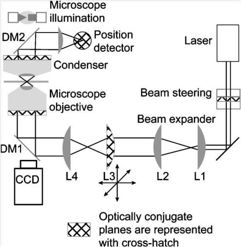
Nowadays many implementations of an optical tweezers are available and there is still a great effort in researching new improved solutions. The simplest configuration uses a Gaussian laser beam, expanded by a system of thin lenses. The beam is then reflected by a mirror and focused on the sample by a microscope objective.

The first working optical trapping scheme, proposed in 1978 and demonstrated in 1986 by A. Ashkin, simply consisted in bringing a laser beam to a diffraction-limited focus using a high numerical aperture lens, such as a microscope objective.
Despite optical tweezers have been successfully used in many applications, the bulky structure of standard optical tweezers, as well as the expensive setup, limit their diffusion among biological labs. In addition, the use of standard optical tweezers in turbid media or in thick samples presents significant challenges, being difficult to achieve the tight focusing necessary for optical trapping. The realization of an optical tweezers based on a single optical fiber would turn this device into a miniaturized and handy diagnostic tool, suitable for many relevant applications, like in vivo biological operations, where standard tweezers cannot be successfully exploited.
The realization of optical tweezers based on optical fibers allows obtaining a miniaturized, versatile and handy tool, suitable for many applications relevant to biology and fundamental physics, such as in vivo biological manipulation or in-vacuum single-particle X-ray spectroscopy. The typical approach for the development of fiber-optical tweezers makes use of two fibers, aligned so that the laser beams exiting from the fibers are counter-propagating along a common optical axis. In this case, the axial scattering forces are counterbalanced, so that is quite easy to obtain a stable optical trap, but the set-up requires a critical alignment between the two fibers and manipulation in three dimensions is quite limited. A single-fiber approach would solve these problems, but as in the standard optical tweezers configuration, a strong focusing of the laser beam is needed to realize the optical trap. The simplest idea is that of building a lens on top of the fiber. Conventional silica fiber tips can be shaped into tapered lenses, but their performance when immersed in a medium such as water depends critically on the radius of curvature of the fiber tip. Since many important systems are dispersed in water, it would be desirable to have fiber tweezers that could work robustly in such a liquid. Since the refractive index of water nw =1.33 is close to that of silica ns =1.45 the focusing of light is not effective, typically resulting in large spot sizes and small working focal lengths. This renders the optical trap ineffective in applications that require trapping of micron-scale particles. Decreasing the radius of curvature of the fiber tip enhances the focusing of light, but also causes light leakage through the fiber cladding, resulting in a decrease in efficiency of the optical trap.
In order to increase the gradient force component, a Gaussian beam must be focused on the particle by a high NA objective so as to counterbalance the scattering force. Moreover, when considering a strongly focused Gaussian beam in ray-optics regime, the central on-axis rays contribute mainly to the scattering force, yielding a negligible contribution to the axial gradient force. As to suppress the on-axis scattering force, we decided to use a bundle of optical fibers with cores aligned along an ideal annulus core and we cut the cores of the fibers at an angle θ so that the propagating light experiences total internal reflection (TIR) at the interface with the surrounding medium. Hence optical beams are first deflected into the cladding and then transmitted out of the fibers converging all in the same point, at a large angle with respect to the fiber axis. The resulting structure provides, for optical trapping purposes, the equivalent effect of a focused beam, with the advantage that the scattering force in the axial direction is highly suppressed. We indicate such tweezers as TIR-based optical fiber tweezers (TOFT).
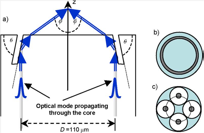
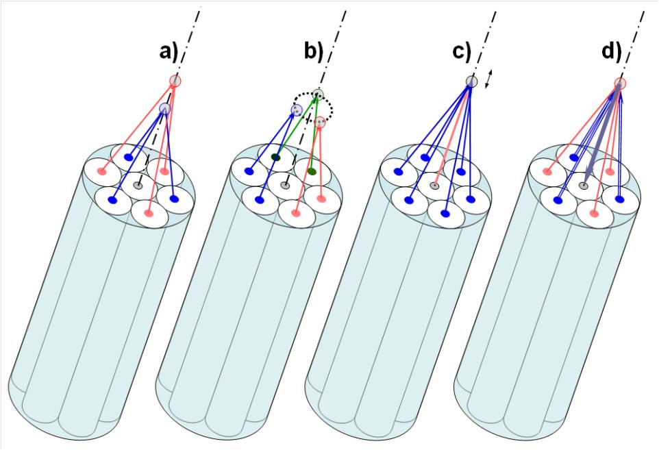
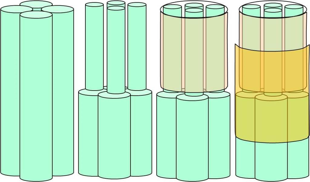
By cutting the fiber surfaces at an angle θ slightly beyond the critical angle for TIR (θc = 66.5°), the structure behaves like an optical system with NAeq = 1.06, a value very close to that of the typical objectives used in bulk optical trapping arrangements. The position of the trapping point can also be easily evaluated through ray optics considerations. If the diameter of the core annulus is, as an example, D = 110 µm, the trapping position is about 40 µm away from the point of TIR, thus allowing a high degree of freedom in sample manipulation. It is possible to fabricate TOFT with more fibers; the result is an increase in the final dimension of the probe, but in this way it is possible to implement additional features. In the figure below we show some example of the possible functions that could be realized using a structure with seven fibers. In a) the possibility to realize multiple traps along the probe axis, just by using a different cutting angle θ on three of the fibers, is shown. A possible steering of the fiber beams necessary to realize multiple traps at the same distance from the probe end is shown in b). As depicted in c), it is also interesting to notice that the radiation pressure that can be exerted, on a trapped particle, by using the light output from the central fiber can be used to slightly modify the trapping position, thus allowing to realize a particle translation or oscillation. Finally in d) a schematic representation of an optical-analysis configuration is used. Some fibers (e.g. those with pink cores in the figure) can be used to trap the particle, while other fibers (blue cores in the example) can optically excite the sample, and the central fiber can be used for the collection of the emitted signal. It is also interesting to notice that different fibers can be used for the different tasks (e.g. a large-mode-area fiber can be used to increase signal collection).
The TOFT fabrication process has been made in collaboration with the BIONEM laboratory of the University of Magna Graecia in Catanzaro and the Istituto Italiano di Tecnologia, IIT, in Genova. It is divided in two separate steps: the first one concern the assembly of the bundle and the second regards the micromachining of the probe so as to obtain the angled surface necessary for total internal reflection.
The first step of the fabrication is realized in the Quantum Electronics Laboratory in Pavia. We take a bundle of four optical fibers with reduced cladding of 80 µm, 2 meter long; the fibers are single mode at 1070 nm, exhibiting a mode field diameter of about 6.1 µm. First we remove the layer of acrylate of the fibers ends, then we insert the four tips in a capillary with an internal diameter of 200 µm. We glue the fibers in position and we insert another bigger capillary with an internal diameter of 650 µm to reduce the fragility of the bundle.
We then fill the gaps between the fibers with an epoxy resin, Epo-Tek 301-2 FL, which, once solid, will held the fibers in position. In order to achieve a better penetration of the resin inside the capillary, we put the probes in a vacuum chamber for 15 minutes, and then we let the air in: the air pressure will push the resin deeper inside the capillary. After three days the resin becomes solid and we can proceed with a polishing machine that will reduce the roughness of the fibers surface under 1 µm, so as to obtain a good optical quality of the fiber surface. The probes are then sent to the BIONEM Laboratory in Catanzaro for the second step of the fabrication process. Up to now two different techniques have been exploited to fabricate the TOFT: in one case the cores of the fibers are cut at the desired angle to achieve total reflective by digging holes in them through a focused ion beam, in the other case four prisms, having the correct angle for beam reflection, are fabricated on the surface of the fibers for the same purpose.
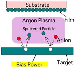
After polishing, the probe is put in a sputtering system to deposit a thin film of gold onto the fibers surfaces. By first creating gaseous plasma and then accelerating the ions from this plasma into a gold target, the material is eroded by the hitting ions via energy transfer and is ejected in the form of neutral particles - either individual atoms, clusters of atoms or molecules. As these neutral particles are ejected, they will travel in a straight line unless they come into contact with the TOFT, coating it with a thin film of about 40 µm.
Once covered by the metal layer, the probe is inserted in a scanning electron microscope (SEM) with a focused ion beam (FIB) tower. While the SEM uses a focused beam of electrons to image the sample in the chamber, a FIB setup instead uses a focused beam of ions to drill holes onto the sample. The FIB uses Liquid-metal ion sources (LMIS), in particular gallium ion sources. Gallium metal is placed in contact with a tungsten needle and heated. Gallium wets the tungsten and an electric field, greater than 10^8 volts per centimeter, causes ionization and field emission of the gallium atoms. Source ions are then accelerated to an energy of 5-50 keV and focused onto the sample by electrostatic lenses. LMIS produces high current density ion beams with very small energy spread. A modern FIB can deliver tens of nA of current to a sample, or can image the sample with a spot size on the order of a few nanometers.
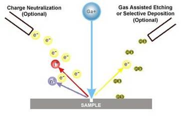
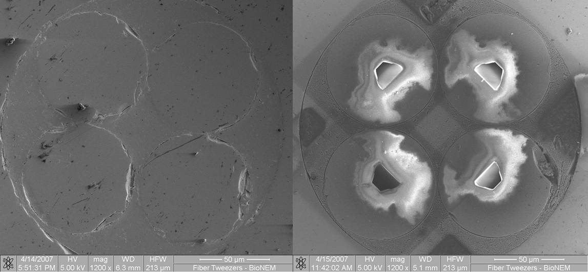
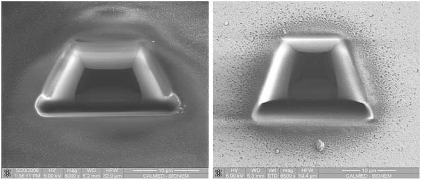
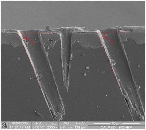
The gallium (Ga+) primary ion beam hits the sample surface and sputters a small amount of material, which leaves the surface as either secondary ions or neutral atoms. The primary beam also produces secondary electrons. As the primary beam rasters on the sample surface, the signal from the sputtered ions or secondary electrons is collected to form an image. At low primary beam currents, very little material is sputtered and the FIB systems can easily achieve 5 nm imaging resolution. At higher primary beam currents, a great deal of material can be removed by sputtering, allowing precision milling of the specimen down to a sub micrometer scale. The fiber-end faces of the TOFT are then microstructured through FIB milling; the core regions at the fiber surfaces are properly shaped in such a way as to obtain TIR at the fiber core/water interface. The image of the micromachined probe, taken at the scanning electron microscope, shows the milling of the four-fiber bundle with a trapezoidal shape, preferred to a rectangular one to minimize the damage to the sample.
The overall structure presents a very good symmetry and the surfaces are of excellent quality, anyway there are some limitations. First of all there are strict conditions on the cutting angle θL, which cannot be under 66,5° in order to have total reflection at the glass-water interface, and over 74° to obtain a gradient force high enough to trap the particle. Another problem is that the cut angle θL cannot be perfectly achieved in the FIB process. Indeed, while the ions dig the core of the fiber at the designed angle, some of the extruded material re-deposes on the hole, thus creating heavy roughness on the core interface. Moreover the ion beam diverges as long as it goes deeper in the fiber, thus varying the cutting angle of the nucleus. Hence, the divergence of the beam and the re-deposition of the extruded material vary the angle θL by ± 1%. The depth of the hole is also crucial, in fact we cannot verify, with the SEM vision, if the cut parameter set in the configuration exactly matches the final cut. The dig duration is quite long, it takes about half an hour for each fiber core; even if it is possible to reduce the time amount adding a gas etching to the ion beam, the result is often destructive for the probe surface. A big effort has been spent in increasing the performance of the optical tweezers fabrication process, in order to achieve better cuts in less time. The first implementation was the change of the dig geometry. First we define two trapezia, the smaller one superimposed to the bigger one. In this way the FIB first excavated the fiber core, obtaining the desired angle and shape, then, with the second trapezium, the dirt deposed on the cut was removed. We also switched to a bigger hole, so that the alignment between the hole and the core was less strict.
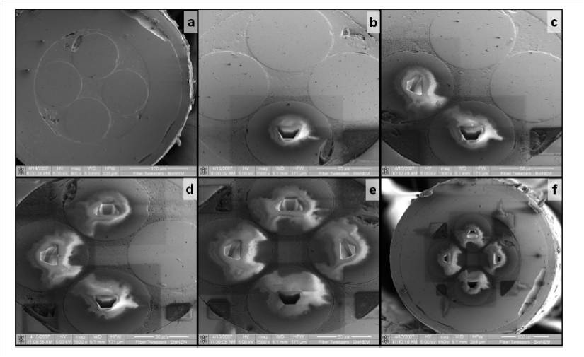
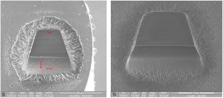
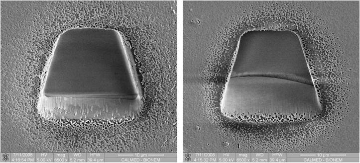
We also changed the sputtering parameters, adding a second layer of Nickel with a thickness of 80 µm on the gold one. In this way the fiber surface became more resistant to the gas etching, allowing the use of XeF2, and reducing the drilling time without compromising the integrity of the tweezers. The different results obtained in the holes fabricated with and without the Nickel layer are shown in the figure below.
Finally, we set a higher beam current, which improved the fabrication time. This way we increased the number of ions hitting the probe, excavating the core more efficiently.
After all these modification of the fabrication process, we verified the realized cutting angle and the depth of the hole. Since it has not been possible to perform this test directly on a TOFT sample, we glued two microscope slides together with a UV resin and we proceeded with the ion milling on the glass-resin-glass interfaces.
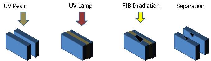
Then we put the glasses in a solution with acetone to remove the UV resin and we inserted one of the glasses in the SEM chamber to observe the side view of the obtained cutting angle.
From this verification we calculated an error of ±1° on the angle, due to the material re-deposed and to the divergence of the beam. The cuts were also deeper respect to the set parameters of about 15%. Thanks to these results, we then readjusted the parameters reducing the milling time. As final result, we reduced the milling time from 26 to 14 minutes/fiber. We tried also to reduce the limitations on the cutting angle θL, by sputtering a layer of 40 nm of Au and Ni on the fibers core of the micro-machined probe, so as to obtain total internal reflection even at lower cut angle. Anyway this coating didn't solve the problem since it was quickly burned by the radiation exiting from the cores under test.
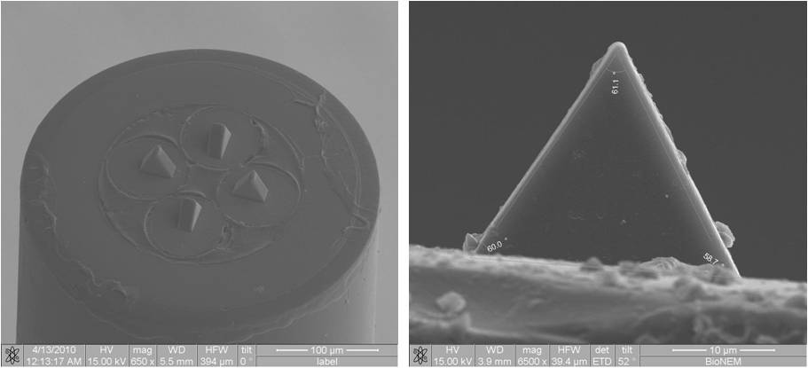
The main limitations of the FIB approach come from the fact that is very difficult, or even impossible, to obtain more complicated geometries, and from the high running costs of FIB equipment. Two-photon polymerization lithography recently showed its ability to create microoptics of arbitrary shape on the end-face of an optical fiber. The micro-prisms fabrication on each of the four fiber cores is performed by using a two-photon lithography setup where a 100-fs pulsewidth, 80-MHz Ti:sapphire laser oscillator is used as the excitation source, and a dry semi-apochromatic microscope objective, NA = 0.70, is used for beam focusing. A specific fiber holder is mounted on a xyz piezo-stage with an 80 µm travel range on all axes, for positioning in horizontal and vertical directions. The fiber holder is designed in such a way to let the laser beam, coming from the microscope objective, to pass through a glass coverslip and then focalize in a photopolymerizable material droplet where the fiber bundle is immersed. A precision linear translator controls the fiber-coverslip distance. A commercial UV curing adhesive (NOA 63, Norland) is used as a photopolymer for fabrication due to its good adhesion to glass, easy processing, suitable refractive index (1.56 for the polymerized resin), and very low cost. The laser wavelength is tuned to around 720 nm and a variable attenuator, made by a half-waveplate and a polarizer, is used to decrease the laser power at the sample plane to 4 mW. The beam is expanded by a telescope, to obtain overfilling of the focusing microscope objective, and is then reflected by a 45° short-pass dichroic mirror which transmits in the visible part of the spectrum for imaging purposes. A lens images the sample, illuminated by using a light-emitting diode (LED) light source, onto a CCD camera for fiber alignment, focusing and real-time monitoring of the polymerization process. A computer-driven mechanical shutter is used to control the exposure time for each pixel. A dedicated Labview-based software was written to convert the point-by-point defined structures into piezo stage positions and to control the synchronization of the movements with the mechanical shutter. The time needed to expose a single microprism is typically around 10 min. After the completion of exposure for all of the four microprisms, the fiber bundle is retracted from the droplet and the photopolymerizable material that did not cross-link is removed by washing for a few seconds with acetone and methanol, leaving the 3-D structure attached to the fiber top. The fabricated solid 3-D microstructures are then observed by using a scanning electron microscope (SEM).
This section reviews the results obtained in testing the TOFT fabricated with both the described technologies. Experiments concerning trapping and manipulation of either dielectric or biological samples are shown.
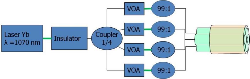
The probes have been first tested by coupling an Yb-doped fiber laser emitting at 1070 nm into the four fibers composing the bundle. The probe fibers are connected to the laser through a 1x4 fiber-optic coupler, and the optical power carried by each fiber is controlled by fiber variable optical attenuators in each path, yielding an extremely compact and stable setup.
At first we controlled that each beam focuses in the same point, thus providing the focusing effect necessary to trap particles. This experiment has been done by observing the beams with a microscope objective with high NA; the focal plane was set so as to see the fiber surfaces at first, then we observed the light distribution on focal planes with a growing distance from the fiber.
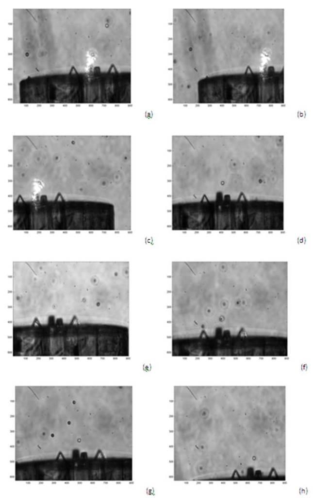
TOFT effectiveness has been then successfully demonstrated by trapping water suspended polystyrene spheres (of refractive index nP = 1.59) having a diameter of 10 µm. We report a sequence of twelve images (obtained using a 10x objective) showing the TOFT and a particle that is first trapped, and then, moved under the microscope objective without escaping from the trapping position. In order to guarantee that the trapping effect was purely optical, we kept the probe at a distance of few millimeters from the cover slip, and we verified that the trapping effect vanished when the light beam was turned off.
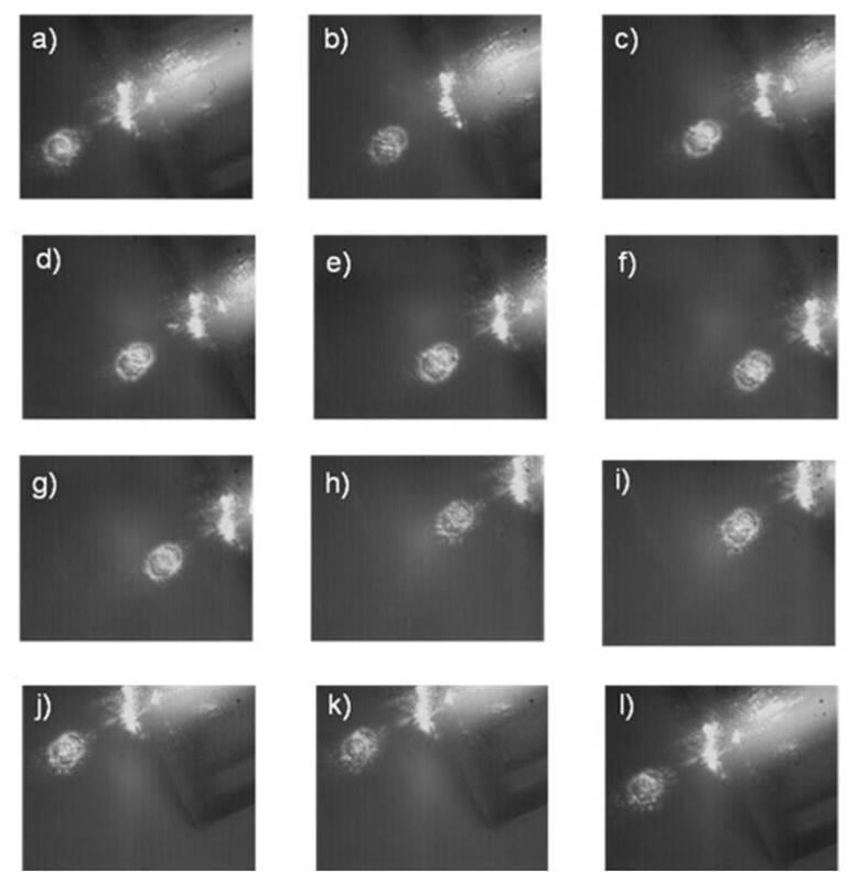
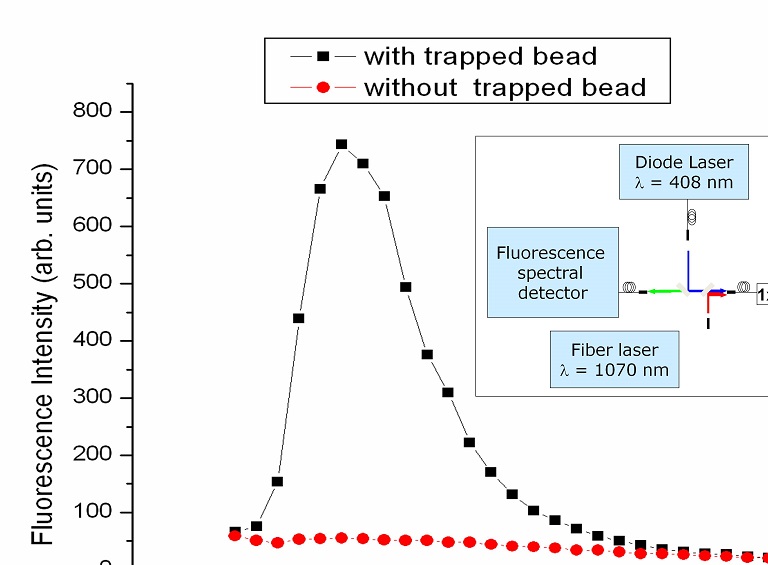
The experimental setup used for the trapping experiment was essentially the same used for the beam characterization with the only exception that the TOFT was mounted on a 3-axis micromanipulator in order to move the trapped particle in a controlled manner. A final experiment has been performed to demonstrate simultaneous particle trapping and optical analysis. The probe end was immersed in a water suspension of 10 µm-diameter fluorescent beads. By using two dichroic mirrors, either trapping or fluorescence excitation radiations (λ = 1070 nm and λ = 408 nm, respectively) were coupled into the fiber probe. The fluorescence signal emitted by the trapped bead was collected by the probe itself, transmitted by the dichroic mirrors, and then detected through a spectrometer with 10-nm spectral resolution. The optical spectra measured with and without a fluorescent bead trapped by the fiber tweezers are reported in the figure below. The optical analysis function is very effective thanks to the short distance between the bead and the probe end, probe-end, which acts both as excitation source and signal collector.
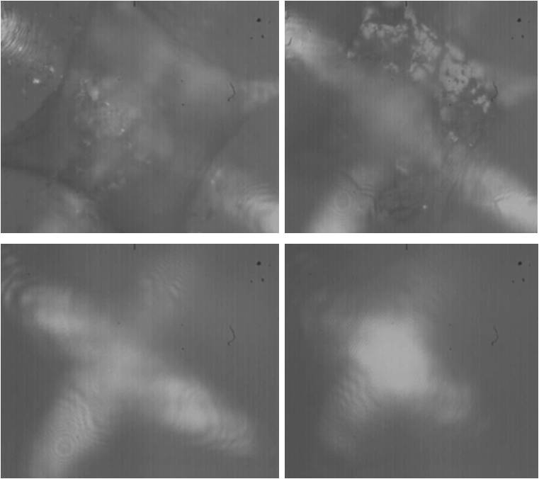
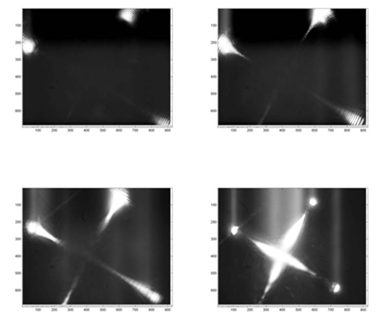
By using the same experimental setup exploited for the characterization of the FIB fabricated TOFT, we evaluated the efficiency of the two-photon lithography fabricated TOFT, by trapping red blood cells and polystyrene beads. Also in this case, we started by verifying the correct focusing of the four fibers. The figure shows four images of the light distribution on focal planes with a growing distance from the fiber. The images are taken with a high NA microscope objective.
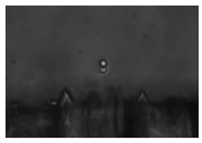
After verifying the correct focusing of the four beams, we performed trapping experiments by using 10 µm polystyrene beads as particles to be trapped. To do so, we put the bundle end face parallel to the microscope slide and, by using a 3-axis micromanipulator, we moved it inside a drop of solution with dielectric particles. After turning the laser on, we were able to trap a particle of polystyrene with all the four beams, and we were able to translate the TOFT without losing the trap.
In order to verify the trapping capabilities of this probe in the biological field, we then tested the device with a solution of red blood cells. In the figure below, the cell has been captured only by a couple of fiber, then we switch to a four-fiber trap by coupling the laser in all the four fiber paths, and finally we continue the trapping experiment by keeping the cell trapped only with the second fiber couple.
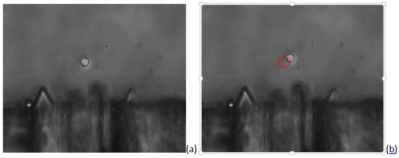
We also managed to fabricate a dual trap TOFT by cutting two couple of prisms at different angles. With this technique we put the basis for multi-trap reliable fiber optical tweezers. We tested a device with the two focusing points distant 10 µm from each other in a 10 µm polystyrene beads solution. We can see the effective trapping of two beads, performed with an optical power of 5 mW exiting from each fiber.
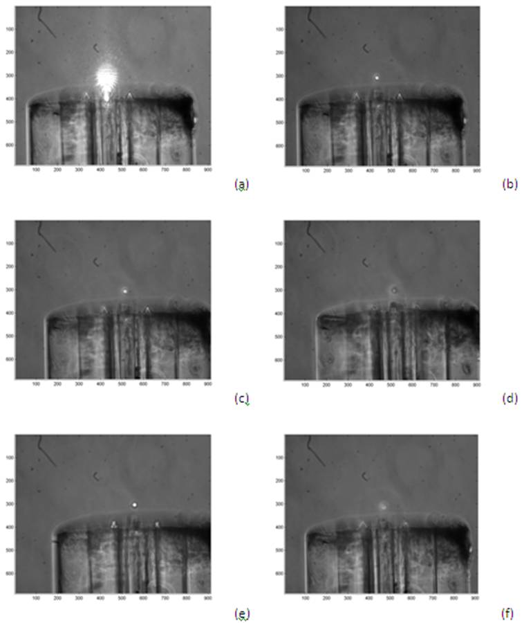
In the figure below we show a sequence of images where the polystyrene bead moves from the nearest trap to the external trap. That is performed trapping the bead with only a couple of fiber, setting to zero the optical power of the second couple by means of variable optical attenuators. Then we abruptly restore the power in the second couple and we set the first one to zero; the particle will be attracted by the new focusing point.
As to conclude, we demonstrated that the fabrication of integrated micromachined optical tweezers led to the first long-distance 3D trapping of micron-sized particles, like red blood cells and polystyrene beads. Both approaches were successfully characterized and tested for trapping, but respect to the other implementation, the external TOFT is cheaper and the fabrication process is faster. Moreover, thanks to the external realization of the prisms, the validation of the refraction angle is far easier and the good adhesion of the UV resin makes this technique very stable.